Full product documentation, content & links
ADC 12-bit ADS1015 4-Channel With PGA Breakout
Qwiic Ecosystem
›
Qwiic Sensors
Sensors & Modules
›
Input & Interaction
Interface
['i2c']
Qwiic
Yes
The ADS1015 ADC converts analog signals to 12-bit digital with 4 channels, ideal for microcontroller projects.
ADC (Analog Digital Converter) is a device that reads analog signals (just like the analogRead () function in Arduino IDE) and converts them into digital signals that can be read by a microcontroller. This breakout is based on the ADS1015 ADC, which reads values in 12-bit resolution, receives a maximum of 3.3V on its inputs and has a total of 4 channels (which can also be used as two differential). Works great with any microcontroller at 5V. It has 2 Qwiic connectors for easier connection on I2C communication.
- Voltage: 3.3V
- Resolution: 12-bit
- Number of channels: 4
- I2C communication
- Dimensions: 22 x 22 mm / 0.9 x 0.9 inch
Interface
| Interface | I2C |
|---|---|
| Qwiic Compatible | Yes |
| I2C Address Default | 0x48 |
| I2C Address Changeable | Yes |
| Breadboard Compatible | Yes |
Measurement
| Measurement Types | Voltage |
|---|---|
| Measurement Accuracy | 12-bit ADC resolution |
Power
| Supply Voltage Min V | 3.3 |
|---|---|
| Supply Voltage Max V | 3.3 |
| Logic Level | 3V3 Only |
| Operating Current (mA) | 0.15 |
Other
| Ic Part Number | ADS1015 |
|---|
Start Here
1
Connect
Plug into any Soldered Dasduino or microcontroller with an easyC cable — no soldering required.
2
Install the library
Add the Soldered library for your language (below).
3
Run an example
Open the get-started example and read your first value.
ArduinoC++
MicroPythonPython
What's in the Box
1×
ADC 12-bit ADS1015 4-Channel With PGA Breakout (main product) 333094
1×
Header pins (unsoldered)
Header pins included for all breadboard-compatible pins
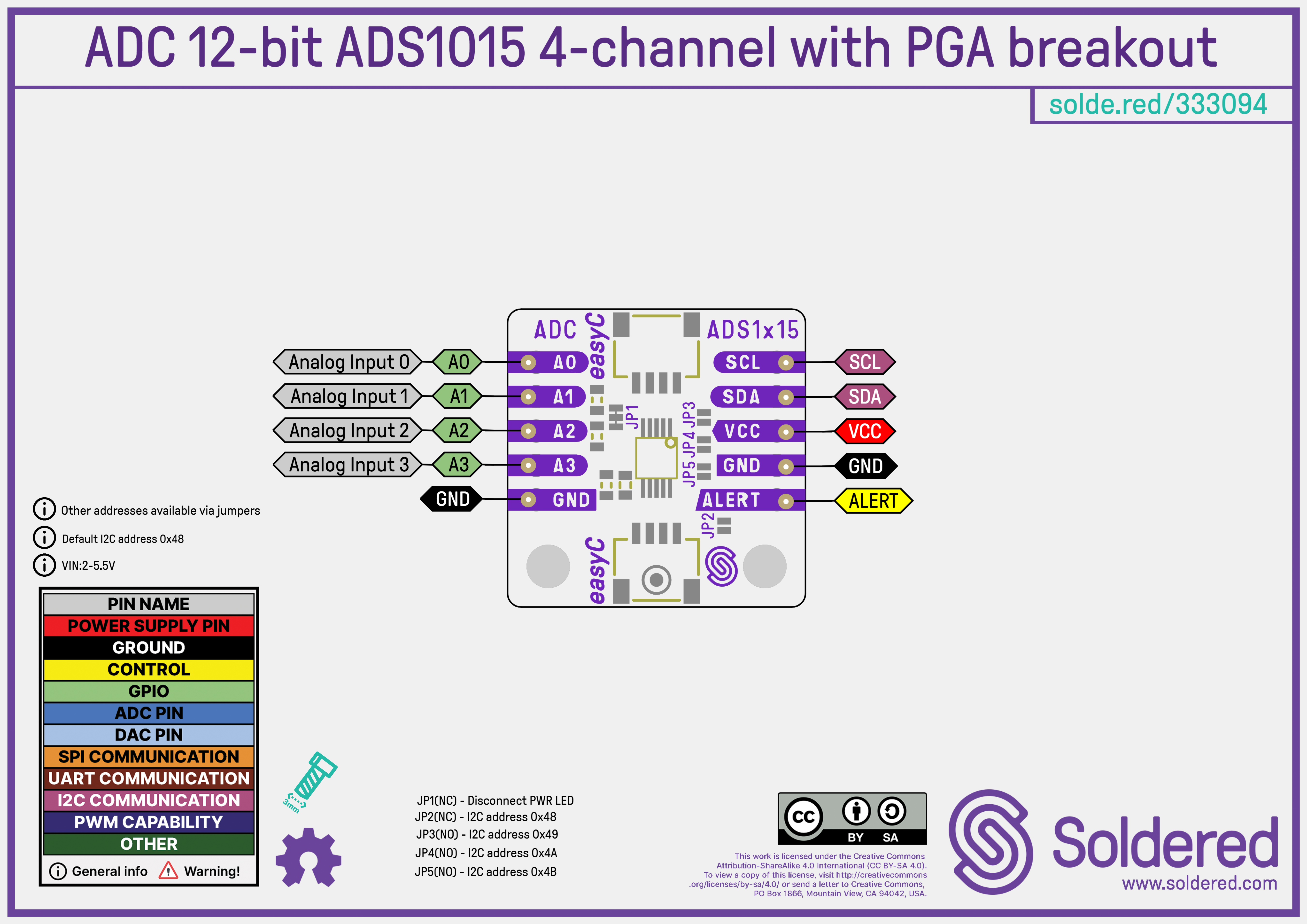
Pinout
Last updated:
Technical Resources
2 resources
Documentation
2 resources
Software Resources
4 resources
Arduino
Arduino Library
GITHUB
Arduino: Get Started
DOCS
MicroPython
MIM Package
WEB
MicroPython Module
GITHUB